Thermal & Material Analysis in Aerospace Manufacturing
Simulated thermographic reconstructions showing how heat behavior and surface properties influence measurement accuracy in alloy forging.
I analyzed multi-alloy aerospace forging lines, investigating thermal drift, emissivity mismatch, and reflection bias across induction heating and infrared systems. During aluminum operations, I identified pyrometer glare faults caused by reflective surfaces and insufficient optical shielding, which led to false readings and unstable temperature data.
Through pyrometry–thermocouple validation, I quantified emissivity bias and recommended matte calibration targets, optical shielding, and angular corrections—upgrades that improved temperature stability, data reliability, and operator confidence in automated monitoring systems.
The visuals below are AI-assisted, NDA-safe thermography simulations created to illustrate real diagnostic findings: reflection paths, sensor misalignment, and emissivity-driven errors that link thermal data to microstructural effects such as pitting and surface variation.
Thermographic Root-Cause Analysis
Pyrometer vs. thermocouple under emissivity mismatch and IR reflection. Visuals are anonymized/simulated and NDA-safe.
Engineering Sketch — Shop Layout (Line Art)
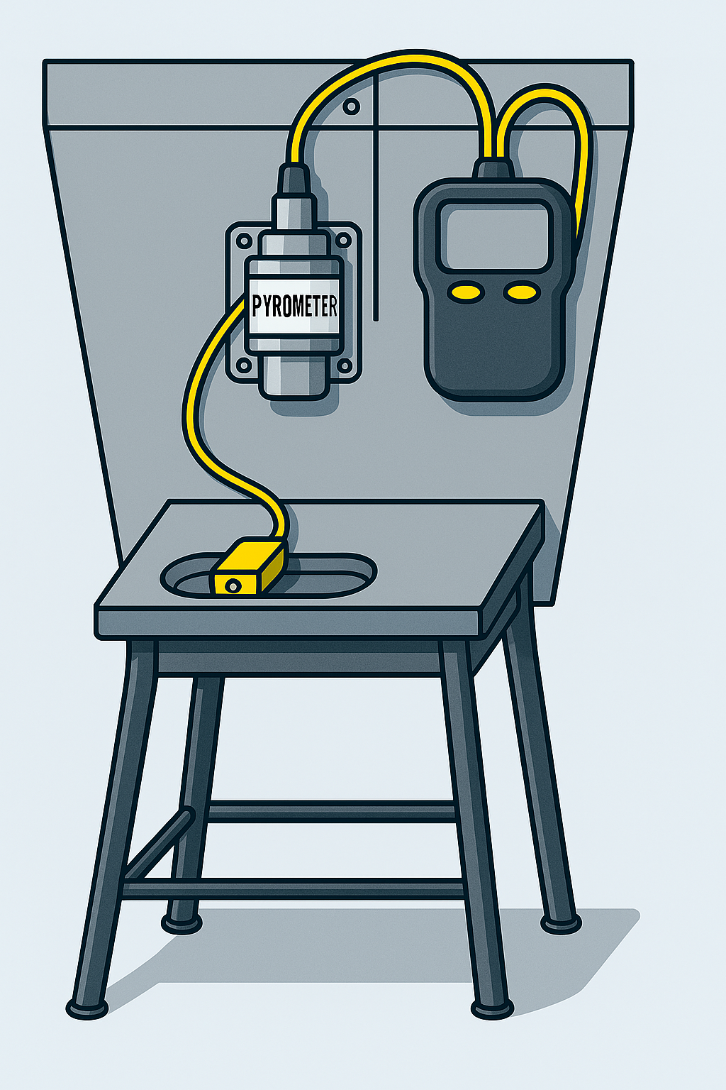
Reference schematic for standoff, perpendicularity, and cable paths used during setup.
AI Visualization — Stand & Sensor Position
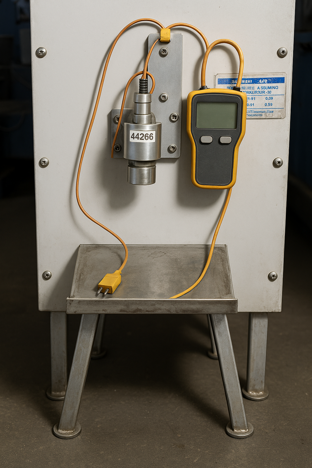
🔍 AI-Generated Visualization — Thermal Measurement Setup
Realistic, NDA-safe rendering of the shop-floor configuration to communicate line-of-sight and mounting geometry without site photos.
The bent platform maintains consistent scan geometry and reduces reflection paths—supporting repeatable preheat measurements.
Representative training visual; no proprietary content disclosed.
NDA-safe rendering conveying geometry and line-of-sight without real-site photography.
Troubleshooting — Pyrometer Reading Bias (Reflection)
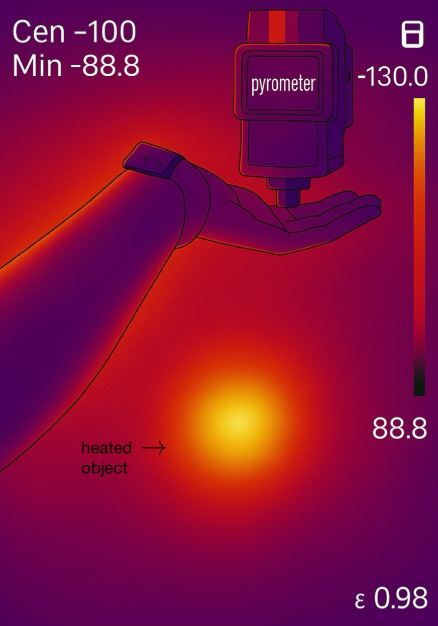
Troubleshooting Pyrometer Errors in Forging Processes
Used hand skin’s known emissivity (~0.98) as a quick reference to confirm ambient/reflection interference. Diagnosis: the sensor was reading reflected radiation at close range, not true surface temperature.
Highly polished aluminum amplifies this effect—often reporting nearby heat signatures. Mitigations: matte targets, angle control, standoff discipline, and shielding.
Collaborated with Fluke and Williamson specialists; proposed optimized mounting, anti-reflective shielding, and recalibration protocols for production use.
Reconstruction for training; multi-site experience summarized without client-specific details.
Polished Al reflected ambient IR into the sensor. Mitigations: matte target, angle control, and shielding.
Concept vs. Simulation — Side-by-Side Overview

Paired view used to verify geometry, line-of-sight, and cable routing. (Concept drawing included here—no duplicate.)
- Reflectivity: Polished Al reflects IR — validate with known-ε target; adjust angle/shielding.
- Placement: Maintain standoff & perpendicularity; remove hot backgrounds from FOV.
- Verification: Cross-check pyrometer with contact spot (black tape) or thermocouple at critical points.
- Safety: Route/guard cables; prefer crush-tolerant preheat methods.
Training reconstructions only; no client identifiers or proprietary geometry shown.