CASE FILE ENTRY // MATERIAL FAILURE LOG
Every defect has a story.
These case studies are fictionalized representations of real-world challenges I encountered in high-precision forging environments. Under the guidance of corporate metallurgists and NDT technicians, I traced failures back to their roots—investigating metallurgical issues like voids, porosity, and inclusions, and evaluating non-destructive testing methods and process flow.
Each reconstruction reflects how I approached failure analysis from the ground up, turning anomalies into actionable insight—while protecting client confidentiality under NDA .
🧪 Metallographic Simulations — Aluminum Alloy
🟦 Subsurface Void Investigation — Aluminum Alloy
- Objective: Investigate machining shifts; voids found near the material boundary.
- Material: Aluminum alloy (simulated)
- Methodology: Cross-sectioned, polished, and examined under 20x lens
Findings:
- Void approx. 0.0004 in wide
- Located near outer edge — likely formed during casting or rolling
Outcome: Helped adjust process control parameters for billet manufacturing.

Void width ≈ 0.0004 in | 20x objective lens
⚪ Simulated Metallographic Analysis — Hydrogen Porosity
This simulated aluminum sample shows a rounded void near the boundary, consistent with hydrogen porosity.
- Magnification: 20x objective lens
- Void diameter: ~0.0006 in
- Observation: Typical of gas entrapment during solidification

Porosity width ≈ 0.0006 in | 20x objective lens
🧪 This example is for educational use only and does not reflect proprietary data.
🧫 Simulated Gas Void — Alternate Morphology
This simulation represents a variation in hydrogen or gas porosity, featuring a more elongated or asymmetrical internal void — a pattern sometimes seen in solidification shrinkage or entrapped gas migration during cooling.
- Magnification: 20x objective lens
- Void type: Elongated/collapsed bubble morphology
- Use case: Failure analysis or process QA

Void feature | 20x objective lens
🧪 This micrograph is a simulation for educational and display purposes only.
⚠️ All visuals are fictionalized simulations and are NDA-safe educational content.
💻 Corrosion Comparison Dashboard
⚫ Pitting Corrosion — 6261-T6 Aluminum
Localized corrosion initiating at microstructural transitions in heat-treated aluminum alloys.
📝 Pit dimensions: 41.2 µm wide × 16.6 µm deep
🔍 Key cue: Irregular, isolated pit with clean matrix around it
- Magnification: 20x objective lens
- Common location: Grain boundaries and heat-affected zones
This is a simulated micrograph. Educational use only.
🟠 Surface Corrosion — 304 Stainless Steel
Uniform corrosion degrading the surface evenly over time.
📏 Depth: ~54.9 µm
🌊 Profile: Shallow, smooth, widespread etching

- Magnification: 20x objective lens
- Cause: Breakdown of chromium-rich oxide layer
Represents typical stainless degradation seen in industrial or outdoor environments.
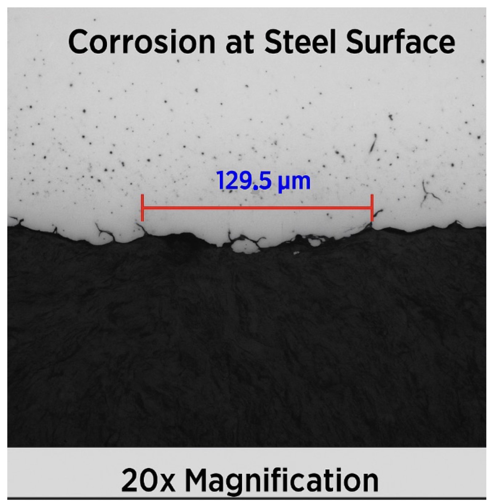
🔵 Advanced Surface Attack — Steel Alloy
Severe corrosion progressing deeper into material with jagged morphology and structural risk.
📏 Penetration depth: ~129.5 µm
⚠️ Visual cue: Uneven edges, trench-like appearance

- Magnification: 20x objective lens
- Cause: Coating failure + mechanical stress + electrolyte entrapment
High-risk failure pattern in structural steel—requires early detection and barrier reinforcement.
📊 Quick Comparison Table
| Material | Corrosion Type | Depth / Size | Visual Cue | Severity |
|---|---|---|---|---|
| 6261-T6 Aluminum | Pitting Corrosion | 41.2 µm × 16.6 µm | Isolated irregular pit | ⚠️ Medium |
| 304 Stainless Steel | Surface Corrosion | ~54.9 µm | Shallow smooth etching | ⚠️ Low |
| Steel Alloy | Advanced Surface Attack | ~129.5 µm | Jagged edge trenching | 🚨 High |
All values are derived from NDA-compliant simulations. For educational and technical illustration only.
🔬 Alpha Case in Titanium — Root Cause & Visuals
Alpha case is a brittle, oxygen-enriched surface layer found in titanium alloys after high-temperature exposure. It must be minimized in aerospace and critical applications.
🧪 Test Method Overview
- Material: Ti-6Al-4V billets, post-forge
- Prep: Polished with 600–1200 grit, etched, LED illuminated
- Magnification: 20x objective lens
- Note: NDA-compliant simulated micrographs
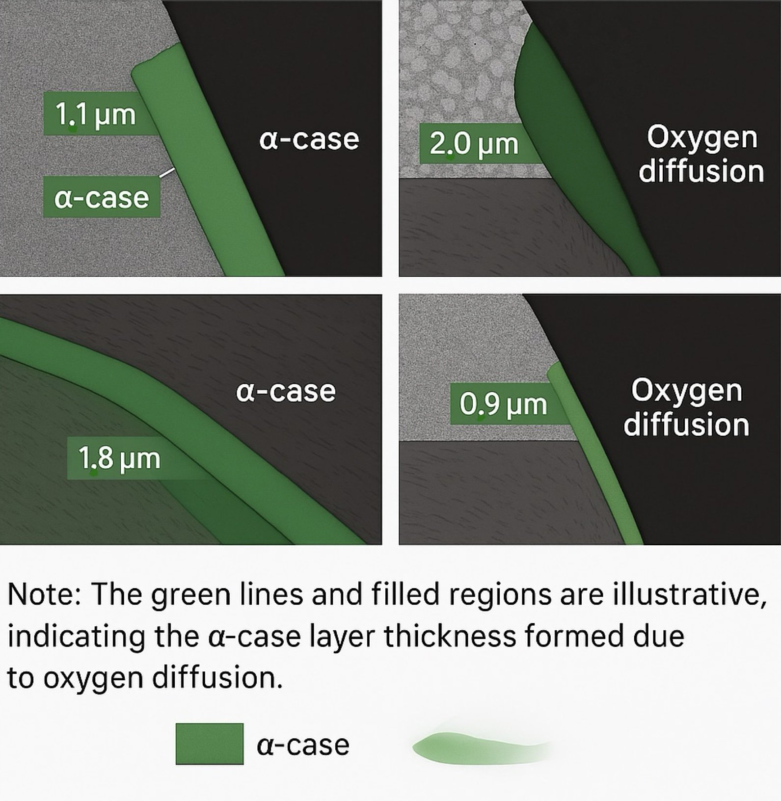
FIG. 1 — Alpha case border region showing oxidized outer layer. Simulated from post-forge billet for root cause illustration.
In this sample, the depth of alpha case infiltration is visibly greater —
2.0 µm
thick — likely due to prolonged exposure or insufficient argon shielding during thermal processing. The surface diffusion profile suggests a parabolic penetration pattern, consistent with Fick’s second law of diffusion under high-temperature, time-dependent conditions.
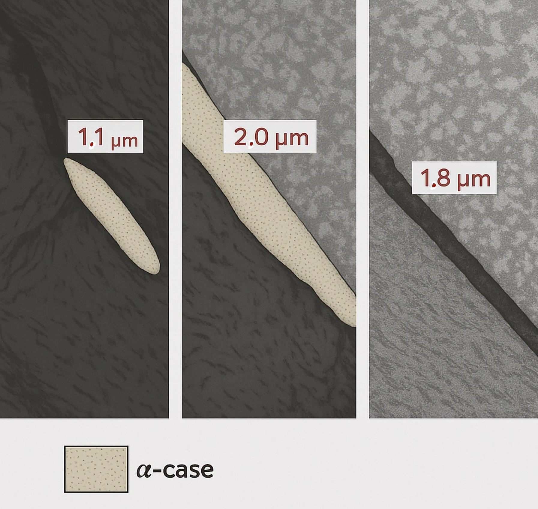
FIG. 2 — Polished cross-section revealing deeper alpha case progression. Simulated for educational analysis.
In this sample, the depth of alpha case infiltration is visibly greater —
2.0 µm
thick — likely due to prolonged exposure or insufficient argon shielding during thermal processing. The surface diffusion profile suggests a parabolic penetration pattern, consistent with Fick’s second law of diffusion under high-temperature, time-dependent conditions.
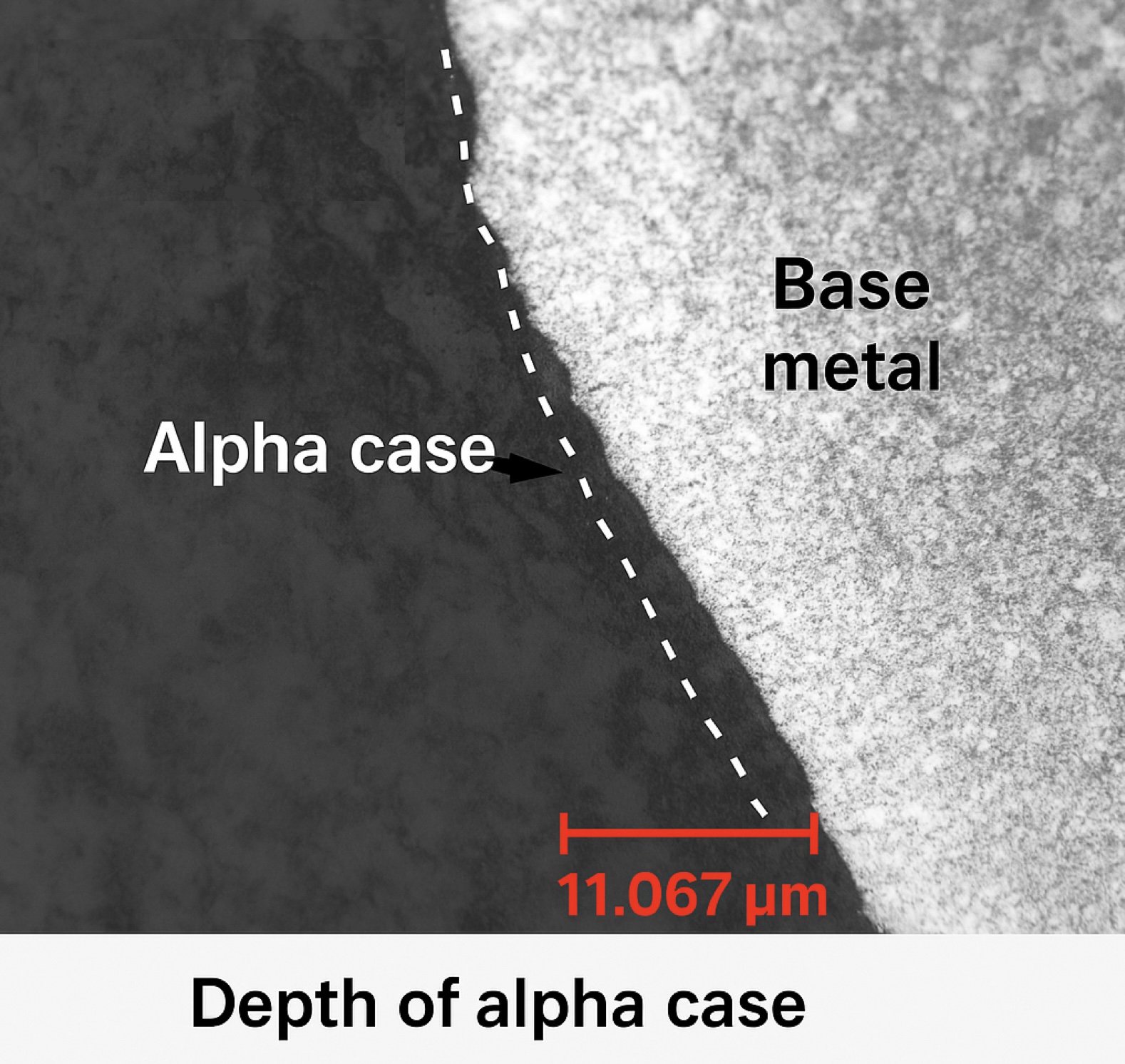
FIG. 3 — Microstructural cross-section showing alpha case boundary etched for visibility.
The outermost light-etching band reveals the oxidized alpha case layer, which diffused inward during thermal exposure.
Note the distinct contrast between base metal and diffusion zone — a key visual indicator when diagnosing titanium surface integrity.
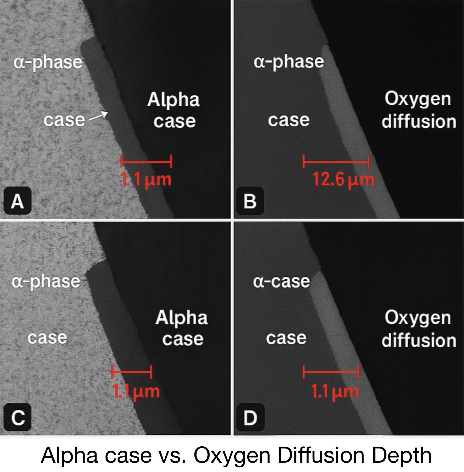
FIG. 4 — Simulated quadrant array illustrating alpha case depth variation in Ti-6Al-4V billets.
Oxidation depth ranges from 1.1 µm to
12.6 µm, depending on thermal exposure and shielding consistency.
This educational figure demonstrates how non-uniform argon flow or furnace cycling can impact surface integrity.
Variability in oxygen diffusion depth is a common root cause of microstructural inconsistency in aerospace forging.

FIG. 5 — Extended exposure case with alpha case thickness nearing upper tolerance. Simulated for analysis training.
Here, the alpha case thickness approaches or exceeds typical removal thresholds (e.g., 0.0015"–0.002"). Without corrective machining or etching, components with this level of diffusion risk embrittlement and premature failure. This visual is useful for identifying where post-processing becomes mandatory to meet aerospace specs.
🛠 Alpha Case Prevention Tips
- Full argon shielding or vacuum processing
- Avoid overheating — control furnace ramp & dwell time
- Use post-forge surface removal (grinding, etching)
- Monitor induction heater frequency, not just temperature
⚖ Alpha Case vs. Pitting
| Trait | Alpha Case | Pitting |
|---|---|---|
| Location | Outer oxidized rim | Local surface voids |
| Cause | Oxygen diffusion at high temps | Gas entrapment, corrosion |
| Appearance | Smooth rim / gray band | Irregular cavities |
| Fix | Grind/etch + shielding | Melt quality & prep |